Without giving it much thought, I went to the car parts store and bought me one of these:


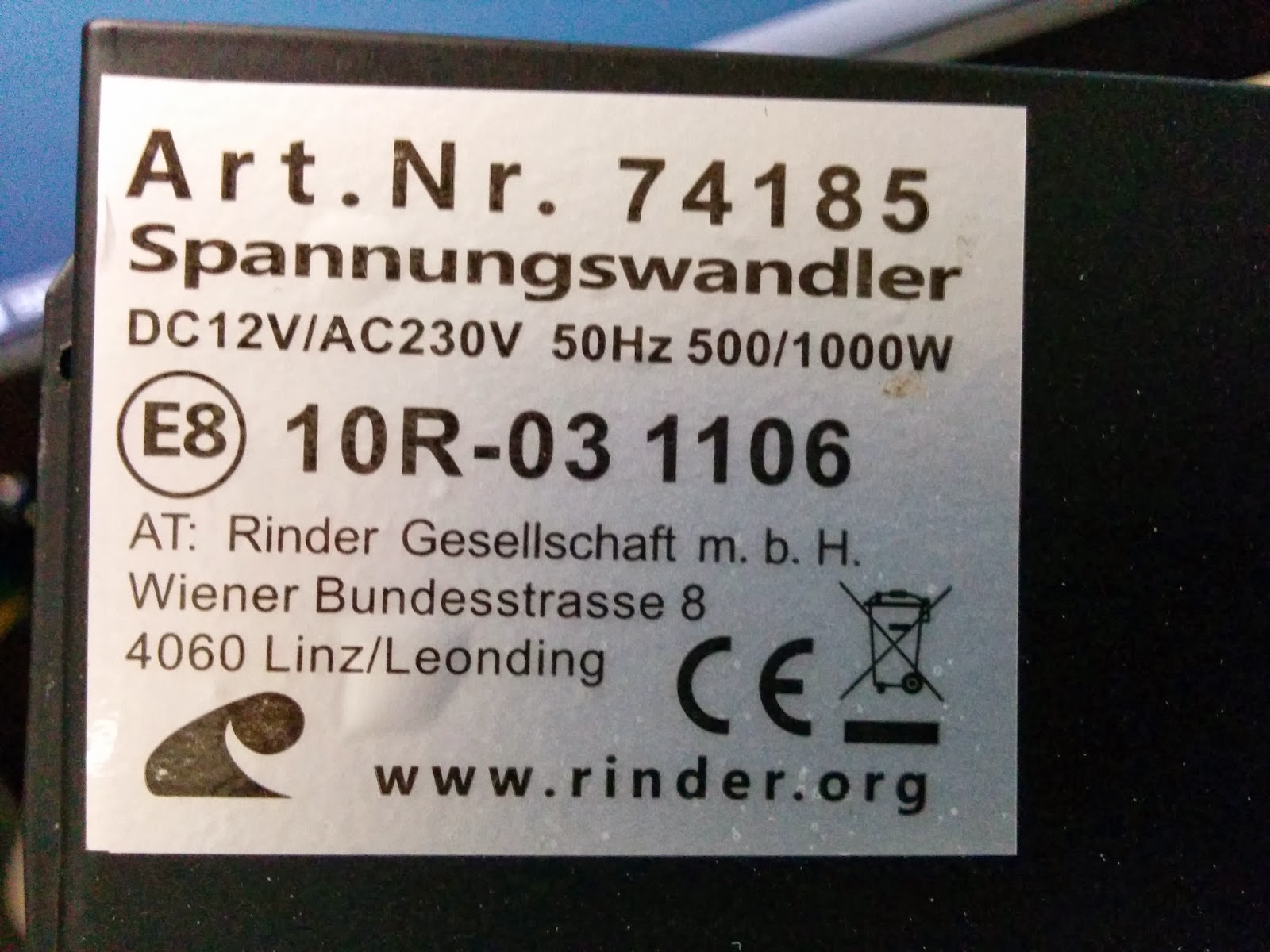
The idea was to convert the 12V DC output of my battery to a good old 230V AC that I could plug my 220V AC to 20V DC laptop adapter in.
First, it's kind of sad to jump through all these hoops just to do a 12VDC to 20VDC step-up, but I was in a rush.
Second, a bit overkill on the power rating side, but you never know what you'll end up needing to hook to your car battery when on a camping trip.
Well ... turns out buying this things was a bad idea: contrary to expectations, the laptop refused to charge.
Back home a couple of days later, I decided to investigate ...
First step, let's tear the box open to see what goes on in there:

At first glance, the inside looks very much like most inverter circuit schematics you cand find on the net:
- A DC input stage on the right and top with a bunch of what's likely foolproofing diodes and noise filtering caps.
- A good old LM324N quad op-amp, maybe used to produce the AC oscillation
- Two ICs that look like voltage regulators or voltage references, codename KA7500B
- A bunch of power transistors hooked up to the case which doubles as a heat-sink. Transistors look like they are organized in push-pull configuration to current-amplify the oscillation.
- A bunch of transformers to do the 12V -> 230V step-up.
- A big fat 400V-rated electrolytic cap, not sure what for, maybe some more filtering.
- The 230V AC output stage.
Yet things don't work.
Time too hook the whole thing up to the scope to see what's going on:

Now let's feed it 12VDC on the DC input side (current limited to 1A, you never know):
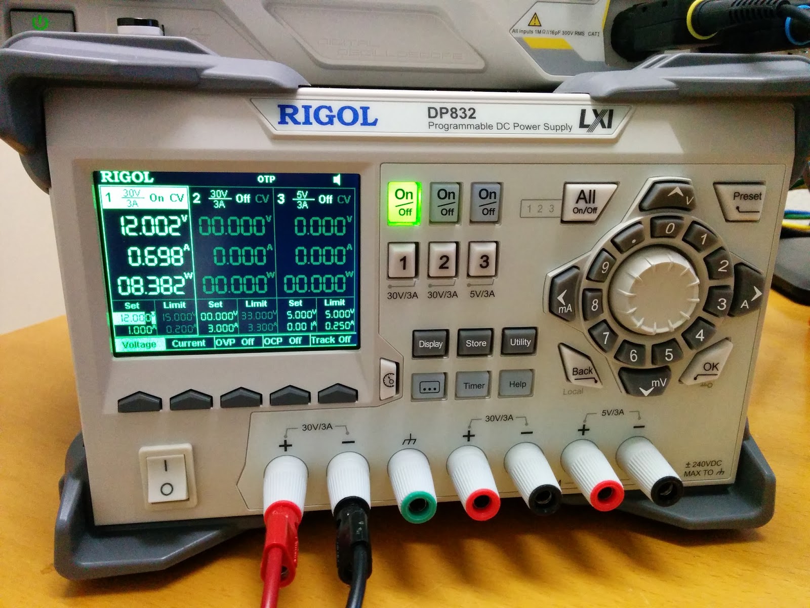
First thing I notice: the darn thing sucks up 8 Watts of power without any load on the AC side :-(
Don't let it hooked to your car battery with the engine off.
Anyhoo, continuing, Fluke says 12V are going in, everything looks good.


Ahah.
And ugh.
So, sure enough, at first glance, we get "mains-like" juice:
- 50Hz says the scope
- 296V plus peak says the scope
- -300V minus peak says the scope
- 244V RMS says the scope (close enough to 230V)
But but but ... the likeness stops there: the waveform is not exactly what I'd call a nice sine wave ... it's in fact an awful bad PWM-like approximation of a sine wave. Yuck.
This is very likely where the problem comes from: I bet my laptop power adapter sorta expects a real sinusodial waveform coming in.
This half-assed approximation of a sine wave is probably making it choke and shut down.
Solution ?
I think there are a few possible avenues:
This is very likely where the problem comes from: I bet my laptop power adapter sorta expects a real sinusodial waveform coming in.
This half-assed approximation of a sine wave is probably making it choke and shut down.
Solution ?
I think there are a few possible avenues:
- Hacking the beast above by adding a large filtering cap after the output. Not confident enough in my electronics skills at this stage, so not going to try it.
- Buying a "pure sine wave" adapter. I guess that's what I should have done, had I thought of doing my research :(
- Buying a DC-to-DC laptop adapter which will at any rate likely be more efficient and more silent (hopefully no large fan and heatsink). Probably something like that.
At any rate, caveat emptor:
If you plan to charge your laptop in your car with a power inverter, you had better triple-check that the so-called "AC output" of the inverter you plan to buy is actually compatible with the input expected by your laptop adapter.
Best way to do this ? Confirm with salesman, buy it, try it, bring back to salesman if it doesn't charge your laptop, iterate.
But don't do what I did and expect it to work simply because the inverter says "230V AC output" and the laptop adapter says "230V AC input".
But don't do what I did and expect it to work simply because the inverter says "230V AC output" and the laptop adapter says "230V AC input".